

CYPECAD MEP is a program for the design of the envelope, distribution and services of the building using an integrated 3D model with the various elements of the building (dwellings, offices, hospitals, teaching centres, shops, residential, etc.). It is composed of several modules or tabs, depending on the different types of installations that can be designed.
The Dynamic fire simulation module, implemented within the Fire (FDS) tab of CYPECAD MEP, is the result of an investigation project financed by the Centro para el Desarrollo Tecnológico Industrial (CDTI), and co‑financed by the European Regional Development Fund (ERDF).
This module of CYPECAD MEP carries out dynamic simulations of the evolution of fires in buildings using two external tools (already installed in the program): the FDS (Fire Dynamics Simulator) analysis motor and the graphics viewer, SmokeView (SMV), both developed by the NIST (National Institute of Standards and Technology, USA). These tools do not have a graphical data introduction interface or a useful and easy to use analytical expression of the results, and so, other tools are required for their use.
CYPE’s Dynamic fire simulation module uses the graphical interface of the CYPECAD MEP program to provide the FDS motor and SmokeView viewer with the correct and required data (without the user having to intervene in this communication). It offers a highly useful analysis of the results, obtained from an exhaustive interpretation of the results calculated by the FDS motor, and all this, without the need of a highly qualified expert in the use of the FDS motor or fire evolution in buildings.
CYPE Ingenieros has carried out a project, financed by the Centro para el Desarrollo Tecnológico Industrial (CDTI), and co-financed by the European Regional Development Fund (ERDF), to implement the Dynamic fire simulation module within the CYPECAD MEP program.
The Dynamic fire simulation module carries out dynamic simulations of fire evolution in buildings. To do so, it uses two external tools (installed within the CYPE program):
- Analysis motor
For the analysis motor, the program uses the computational fluid dynamics model known as FDS (Fire Dynamics Simulator), developed by the NIST (National Institute of Standards and Technology, USA). - 3D viewer
For the 3D graphics viewer of the evolution of the fire, SmokeView (SMV) is used, also developed by NIST.
Neither tool has a graphical data introduction interface, and so the data must be introduced using text files organised in a specific way. On the other hand, the FDS motor generates, within its analysis process, a large amount of information on the fire simulation which has been undertaken. The analysis of this information is highly complex and laborious, and requires vast experience on behalf of the user to be able to express it in a useful manner.
CYPE’s Dynamic fire simulation module uses the graphical interface of its CYPECAD MEP software to provide the FDS motor with the correct and required data, and the SmokeView viewer with the necessary results for a 3D animation of the results to be obtained. All this, without the user having to intervene. CYPE’s program also analyses and interprets the results which have been calculated by the FDS motor and generates control points which appear on the plan view of the Fire (FDS) tab of the CYPECAD MEP program, where the user can obtain reports containing time graphs of the evolution of the variables monitored in the simulation.
The Dynamic fire simulation module allows the user to locate the seat of the fire at any point in the building to validate the behaviour of the smoke of the fire and check the viability of the evacuation. It can also be used for existing buildings, allowing the user to verify if the design of the building can be improved even if it already fulfils the requirements of the corresponding code.
There are many factors which influence the safety of the building in case of a fire. Amongst them is the concentration and temperature of the smoke, as high levels can hinder the correct evacuation, risk the integrity of the occupants, and even aid in the structural collapse of the building. The width of the corridors, the quality of the materials and fire protection installation are some of the parameters this software takes into account, and are linked to all the CYPECAD MEP programs developed by CYPE. This allows the user to check and visualise the design alongside the corresponding design code.
There is currently no other similar technology, and so the program can be of great use to Fire fighters and engineers responsible for the design of fire suppression systems and temperature control and smoke evacuation systems.
More detailed information on the data introduction and the results provided by CYPE’s Dynamic fire simulation module can be found in the following sections.
Operating the Dynamic fire simulation module
Activating the analysis and required data for the dynamic simulation
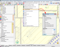
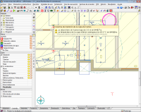
The analysis of the simulation is carried out within the Fire (FDS) tab of the CYPECAD MEP program. Within the FDS menu of this tab, all the options required to define the simulation can be found (except the Fire loads option which can be found in the Installation menu within the same tab). These options are usually defined before the analysis. Nonetheless, the simulation can be initiated at any moment using the Analyse fire simulation option within the FDS menu (even if no other parameters have been defined) and the program will emit a warning indicating there is data missing: definition of fire scenarios, selection of building precincts to be included in the simulation, definition of fire loads and selection of the fire initiation element.
Additionally, to analyse the dynamic simulation of the building, the construction elements of the building must be introduced, as well as defining its precincts and, if required, fire installation protection elements such as automatic sprinklers, fire or smoke detectors are also to be introduced and are processed as such in the FDS model. If the evacuation paths are also defined, the program monitors the evolution of the smoke along the evacuation paths, which provides valuable information on the evolution of the temperature and smoke at places crossed by those paths.
Introduction of the specific data for the dynamic simulation
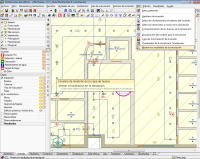
 To define the scene of the simulation correctly, the combustible elements occupying or furnishing the precincts where the fire will develop or can extend to, have to be introduced in the model, as these will be the main fire loads which feed and determine how the fire will evolve.
For this, the program includes a tool to introduce the combustible solids (Installation > Fire loads), with an associated common combustible materials library, containing the required data for the FDS model, such as combustion and vaporisation enthalpies, pyrolysis, heat release rates, loss of mass, etc.
The construction elements making up the geometric model of the building are characterised automatically in the FDS model, achieving a simple, easy and intuitive introduction of the combustible and non-combustible elements in the simulation.
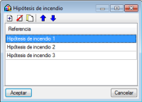
To create the fire models which the FDS motor will analyse, a tool can be used which manages the different fire scenarios in the building, so that, in a single file for the whole building, different fire scenarios and their corresponding results from the dynamic simulation can be managed. This way, data introduction is greatly simplified and the elaboration of new fire scenarios and the analysis of each of their results can be carried out in a more agile manner. This also allows the user to compare and analyse different fire scenarios within the building, to obtain a better understanding of the positive aspects and errors of the design, and so reaching the most optimum configuration for temperature control and smoke evacuation.
These fire scenarios are created using the Fire scenario option within the FDS menu. The program allows the user to create, copy and edit the different fire scenarios of the building, and select any of them and work on their associated data, which includes:
- Selection of the building precincts
This selection is carried out using the following menu: Selection of precincts to include in the simulation, within the FDS menu. The number of precincts included in the simulation will determine the size of the model which is launched in the analysis, and hence, the time required to analyse it. - Selection of the elements initiating the fire
The selection of the load or fire loads which begin to burn at the start of the simulation is carried out using the following option: Selection of fire initiation elements, within the FDS menu. - Status of the openings
The status (whether open or closed) of the openings present in the building, such as doors or windows, will determine the air flow of the fire and, therefore, its evolution. To open or close an opening, use the following option: Behaviour of openings in the simulation, within the FDS menu.
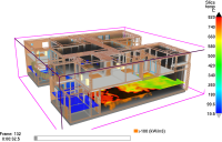
Apart from this information, the FDS model that is generated for each fire scenario includes control logics which allow for certain changes to be carried out on the model during the simulation. So, windows or skylights which start off as closed in the simulation, can break at a particular moment of the simulation if the necessary pressure and temperature conditions arise, and so the ventilation conditions can vary during the simulation. Additionally, if sprinklers or heat or smoke detectors have been defined, these are linked with a logic which simulates the fire alarm signal of the building, with some delay, which allows to act upon other elements of the building, such as closing of magnetic retention firebreak doors or the opening of smoke vents for smoke evacuation at roof level. The video displays an example of the simulation carried out by the program. Here, it can be seen how at a particular moment, the smoke vents on the roofs open (with the consequent reduction of the accumulated smoke layer inside the warehouse) and the sprinklers of the fire protection installation come into action.
Having introduced all the necessary data correctly, and using the Analyse fire simulation option from the FDS menu, any of the defined fire scenarios can be analysed. Upon executing this option, the General data configuration window will open, together with the list of fire scenarios defined for the building.
Within this window, the only thing left to do is choose the scenario to simulate and define two essential parameters for the analysis of the dynamic simulation: the cell size of the mesh of the FDS model and the duration of the simulation.
The cell size for the discretisation defines the precision of the mesh of the building FDS model and determines the number of cells the analysis must manage, which is directly proportional to the time taken to analyse the simulation and the memory space required to carry it out.
15, 20 or 25 cm cell size values are considered to be sufficiently precise to analyse the behaviour of the smoke of the fire in large volumes. Nonetheless, in early phases of the behavioural study of the building on fire, faster simulations can be undertaken by introducing higher mesh values. Sizes smaller than 15 cm imply a very dense analysis and are only required for fire and smoke analysis studies in reduced volumes.
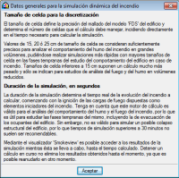
The duration of the simulation determines the real time of the fire evolution to analyse and begins with the ignition of the fire loads established as the initiation elements. The FDS analysis motor is valid to analyse the behaviour of the smoke and fire, and so is useful to study its early phases, including the evacuation of the occupants of the building. However, it is not valid to simulate the possible structural collapse of the building, and so simulations which last longer than 30 minutes are not recommended or necessary.
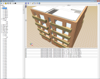
A feature worth highlighting of the program, compared to other modelling tools for the FDS, is the complete independence of the building model with respect to the cell size and mesh of the FDS model. In other words, the 3D model of the building, which is managed and edited in the program (shared with the other CYPECAD MEP analysis models) corresponds to the model with the real dimensions of each element present within it; and the model that is exported to the FDS motor (which is created automatically when the dynamic simulation of the building is initiated) is specific for the scenario selected by the user (with the precinct subgroup it contains and the chosen discretisation), and is optimised for the number of processors used in the analysis and for the configuration of construction and combustible elements present in the simulation.
This manner of working allows the user to forget many of the limitations of the FDS model, such as the alignment of the meshes or having to define obstacles (OBST entities of the model), as the program builds the model adjusting itself to the chosen cell size, modifying the thermal properties of the materials or objects, in such a way that the resultant model can be analysed without any problems for the FDS motor, in a minimum amount of time, and respecting the thermal behaviour of the real model. This presents an obvious advantage for the study of the dynamic behaviour of the fire within the building: it allows for different versions of the model to be simulated, with more or less details (i.e. more or less complex to analyse) by simply varying the cell size.
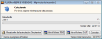
Once the model for the FDS has been created, a window will open automatically which manages the dynamic analysis. The program uses the optimum FDS motor in the computer at which it is executed (32 or 64 bit and with processors in one or several CPUs). The last version of the Dynamic fire simulation program always includes the last validated version of the FDS published by the NIST.
This manager window of the FDS analysis is opened as an independent process, which allows the user to continue working on the model, defining other fire scenarios or buildings, whilst the analysis of the simulation is taking place.
Within this window, the user can view the duration of the simulation analysis, and the estimated remaining time; the real duration of the achieved simulation; buttons to view the generated *.fds file and, launched for the simulation, the output file, *.out, which is generated by the FDS motor; and the button to activate SmokeView with the data of the simulation on course.
Using SmokeView, which has been developed by the NIST and is partner of the FDS analysis motor, the results of the simulation can be accessed up to the analyses moment whilst the analysis is still taking place. This allows for the evolution of the smoke with time to be explored as well as the fire temperature, in a completely 3D visual manner, as well as allowing the user to study the repose of the detection and alarm systems of the building or, even, the activating and working of the automatic sprinklers.
From the management window of the dynamic simulation analysis, the analysis on course can also be stopped and results can be obtained as of the first instant of the simulation up to the moment reached in the analysis. It is also possible to continue with the analysis as of the moment it was stopped, allowing for it to be dealt with in different stages.
Results within the CYPE program
After the analysis, the FDS motor generates a vast amount of information on the fire simulation that has been carried out. The analysis of this information is highly complex and laborious, and requires a lot of experience on behalf of the user to be able to express it in a useful way. The Dynamic fire simulation module contains a tool which post-processes and generates the results of the simulation carried out by the FDS motor so it can be analysed with the CYPE program.
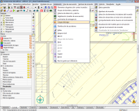
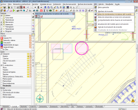
This tool can be activated using the Show simulation results option within the FDS menu. Once activated (in jobs with completely analysed fire scenarios or paused at a particular moment), control points appear on the plan view of the building. Depending on the control point at which the user places the cursor, the following information appears on screen:
- Activation of smoke or heat detectors
- Activation of sprinklers
- Along the evacuation paths, the following are displayed:
- The instants when dangerous temperatures are exceeded in the smoke layer
- When the smoke-free height falls below 2m
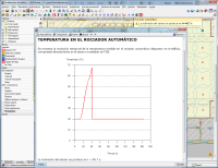
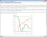
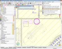
By clicking on any of these control points using the left mouse button, reports are generated, which include graphs that display how the following factors evolve in time during the simulation:
- The temperature in sprinklers or heat detectors
- The degree of darkness in smoke detectors
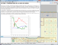
- The temperatures of the cold layer and smoke layer, and the smoke free height (parameters which are required for the SCTECH design in accordance with EN 12101-5:2005) along the established evacuation paths of the building.
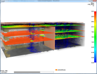
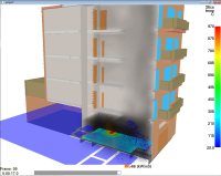
Apart from the control points and columns generated within the FDS model, which are then post-processed to obtain results graphs in the program, upon generating the FDS model, certain control planes are added so they can be inspected in the SmokeView viewer.
For each floor of the building which is analysed in the simulation, temperature distribution planes are added, as well as air velocity control planes and visibility defree planes in metres. This way, within the SmokeViw viewer, as well as the being able to represent the smoke and fire which is generated, the evolution of these magnitudes in horizontal planes can also be represented per floor. Therefore, with this tool, the user can rapidly judge how the building and its smoke evacuation and temperature control systems behave.
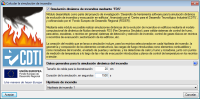
Recommended hardware and software
The complexity of a fire dynamics simulation of a building and the multiple factors which intervene, implies the computer at which the simulation is going to be analysed has more hardware and software requirements than those required to operate normal programs. Emphasis is especially given to the possibility of using processors with several nuclei and the operating system of the computer where the simulation is going to be analysed.
The Dynamic fire simulation module can work with another module of CYPE, Parallel analysis with up to eight processors. This way the user can make the most of the division capacity of the analysis work of the simulation in different FDS model meshes so it can be processed in parallel and that of modern CPUs containing several nuclei, and the lengthy analysis time of the dynamic fire simulations is reduced. To be able to carry out complex simulations, it is essential CYPE’s Parallel analysis with up to eight processors module be included in the user license.
Both the FDS analysis motor and the SmokeView results viewer work on computers with 64 bit operating systems, and so it is possible to carry out complex simulations with a high number of cells which are generated, either due to the building zone which is to be simulated, or because of the reduced size of a unit cell. Thanks to this, the RAM memory restrictions imposed on 32 bit processors (2 GB per process) are eliminated.
Simulation models containing more than 2 million cells cause memory problems to arise in 32 bit operating systems. The program emits a warning of this upon generating the model, which allows the user to correct the size of the zone to simulate, or increase the unit cell size, so to create a mesh with a lower number of cells.
In any case, to be able to carry out complex simulations, either due to their large size or their dense mesh, or because automatic extinguishing systems come into use in the simulation (fire extinguishing using automatic sprinklers), it is always recommended that 64 bit operating systems be used and if possible these be associated with a CPU with several nuclei and a RAM memory greater than 4 GB.
Tel. USA (+1) 202 569 8902 // UK (+44) 20 3608 1448 // Spain (+34) 965 922 550 - Fax (+34) 965 124 950